0
0
 0
0
Your basket is empty...
Chromatography
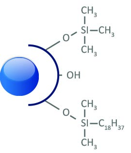
HPLC Phases
ARION - CHROMSERVIS
| Packing Material | Particle Size (µm) | Pore Size (Å) | Surface Area (m2/g) | Carbon Load (%) | pH Range |
|---|---|---|---|---|---|
| Plus C18 | 1.7, 2.2, 3, 5, 10, 15 | 100 | 420 | 18 | 1.5-10 |
| Polar C18 | 2.2, 3, 5, 10, 15 | 120 | 325 | 16 | 1.5-7.0 |
| C8 | 3, 5 | 120 | 325 | 11 | 2.0-7.0 |
| Phenyl-butyl | 2.2, 3, 5 | 100 | 300 | 12 | 1.5-7.5 |
| NH2 | 2.2, 3, 5 | 120 | 325 | 5 | 2.0-6.5 |
| CN | 3, 5, 10 | 120 | 325 | 8 | 2.0-7.0 |
| HILIC Plus | 2.2, 3, 5 | 120 | 420 | - | 1.5-7.0 |
| Si | 2.2, 3, 5, 10 | 100 | 420 | - | 1.5-7.0 |
More information is available at www.arionchromatography.com. You will find Column care guide there.
CHROMSHELL - CHROMSERVIS
| Packing Material | Particle Size (µm) | Pore Size (Å) | Surface Area (m2/g) | Carbon Load (%) | pH Range |
|---|---|---|---|---|---|
| CHROMSHELL® C18 Plus | 2.6 | 85 | 130 | 9 | 1.5-7.5 |
| CHROMSHELL® C18-XB | 2.6 | 85 | 130 | 8 | 1.5-8.0 |
| CHROMSHELL® C18-AB | 2.6 | 85 | 130 | 6 | 1.5-8.0 |
| CHROMSHELL® C18 Polar | 2.6 | 85 | 130 | 6.5 | 1.5-7.0 |
| CHROMSHELL® HILIC | 2.6 | 85 | 130 | - | 1.5-7.0 |
| CHROMSHELL® Si | 2.6 | 85 | 130 | - | 1.5-7.0 |
KINETEX - PHENOMENEX
| Packing Material | Particle Size (µm) | Pore Size (Å) | Effective Surface Area (m2/g) | Carbon Load (%) | pH Range |
|---|---|---|---|---|---|
| Kinetex XB-C18 | 5, 2.6 | 100 | 200 | 10 | 1.5-8.5* |
| Kinetex C18 | 5, 2.6 | 100 | 200 | 12 | 1.5-8.5* |
| Kinetex C8 | 2.6 | 100 | 200 | 8 | 1.5-8.5* |
| Kinetex PFP | 5, 2.6 | 100 | 200 | 9 | 1.5-8.5* |
| Kinetex HILIC | 2.6 | 100 | 200 | 0 | 2.0-7.5 |
| Kinetex Phenyl-Hexyl | 5, 2.6 | 100 | 200 | 11 | 1.5-8.5* |
* Columns are pH stable from 1.5 to 10 under isocratic conditions. Columns are pH stable from 1.5 to 8.5 under gradient conditions.
Kinetex 2.6µm columns with ID 2.1mm are pressure stable up to 1000 bar, otherwise up to 600 bar.
Kinetec chore-shell colums can be replace by new ChromShell colums. Just try it.
LUNA - PHENOMENEX
| Packing Material | Particle Size (µm) | Pore Size (Å) | Surface Area (m2/g) | Carbon Load (%) | pH Range | USP Packing |
|---|---|---|---|---|---|---|
| Luna Phenyl-Hexyl | 3,5,10,15 | 100 | 400 | 17.5 | 1.5-10.0 | L11 |
| Luna Silica (2) | 3,5,10,15 | 100 | 400 | - | - | L3 |
| Luna C5 | 5,10 | 100 | 440 | 12.5 | 1.5-10.0 | - |
| Luna C8 | 5,10 | 100 | 440 | 14.75 | 1.5-10.0 | L7 |
| Luna C8 (2) | 3,5,10,15 | 100 | 400 | 13.5 | 1.5-10.0 | L7 |
| Luna C18 | 5,10 | 100 | 440 | 19 | 1.5-10.0 | L1 |
| Luna C18 (2) | 2.5,3,5,10,15 | 100 | 400 | 17.5 | 1.5-10.0 | L1 |
| Luna CN | 3,5,10 | 100 | 400 | 7.0 | 1.5-10.0 | L10 |
| Luna NH2 | 3,5,10 | 100 | 400 | 9.5 | 1.5-11.0 | L8 |
| Luna SCX | 5,10 | 100 | 400 | 0.55% Sulfur Load | 2.0-7.0 | L9 |
| Luna HILIC | 3,5 | 200 | 200 | - | 1.5-8.0 | - |
| Luna PFP(2) | 3 5 | 100 | 400 | 5.7 | 1.5-8.0 | L43 |
GEMINI - PHENOMENEX
| Packing Material | Particle Size (µm) | Pore Size (Å) | Surface Area (m2/g) | Carbon Load (%) | pH Range | USP Packing |
|---|---|---|---|---|---|---|
| Gemini C18 | 3,5,10 | 110 | 375 | 14 | 1.0-12.0 | L1 |
| Gemini C6-Phenyl | 3,5 | 110 | 375 | 12 | 1.0-12.0 | L11 |
| Gemini NX | 3,5,10 | 110 | 375 | 14 | 1.0-12.0 | L1 |
SYNERGI - PHENOMENEX
| Packing Material | Particle Size (µm) | Pore Size (Å) | Surface Area (m2/g) | Carbon Load (%) | pH Range | USP Packing |
|---|---|---|---|---|---|---|
| Synergi Max-RP | 2.5 | 100 | 400 | 17 | 1.5-10.0 | - |
| Synergi Hydro-RP | 2.5 | 100 | 400 | 19 | 1.5-7.5 | L1 |
| Synergi Polar-RP | 2.5 | 100 | 440 | 11 | 1.5-7.0 | L11 |
| Synergi Fusion-RP | 2.5 | 100 | 440 | 12 | 1.5-10.0 | L1 |
| Synergi Max-RP | 4,10 | 80 | 475 | 17 | 1.5-10.0 | - |
| Synergi Hydro-RP | 4,10 | 80 | 475 | 19 | 1.5-7.5 | L1 |
| Synergi Polar-RP | 4,10 | 80 | 475 | 11 | 1.5-7.0 | L11 |
| Synergi Fusion-RP | 4,10 | 80 | 475 | 12 | 1.5-10.0 | L1 |
ONYX - PHENOMENEX
| Packing Material | Macropore Size (µm) | Pore Size (Å) | Surface Area (m2/g) | Carbon Load (%) | pH Range | USP Packing |
|---|---|---|---|---|---|---|
| Onyx Silica | 2 | 130 | 300 | 0 | 2.0-7.5 | - |
| Onyx C8 | 2 | 130 | 300 | 11 | 2.0-7.5 | - |
| Onyx C18 | 2 | 130 | 300 | 18 | 2.0-7.5 | - |
JUPITER - PHENOMENEX
| Packing Material | Particle Size (µm) | Pore Size (Å) | Surface Area (m2/g) | Carbon Load (%) | pH Range | USP Packing |
|---|---|---|---|---|---|---|
| Jupiter C4 | 5,10,15 | 300 | 170 | 5.0 | 1.5-10.0 | L26 |
| Jupiter C5 | 5,10,15 | 300 | 170 | 5.5 | 1.5-10.0 | - |
| Jupiter C18 | 5,10,15 | 300 | 170 | 13.3 | 1.5-10.0 | L1 |
| Jupiter Proteo C12 | 4,10 | 90 | 475 | 15.0 | 1.5-10.0 | - |
GraceSmart - GRACE
| Packing Material | Particle Size (µm) | Pore Size (Å) | Surface Area (m2/g) | Carbon Load (%) | pH Range | USP Packing |
|---|---|---|---|---|---|---|
| GraceSmart C18 | 3,5 | 120 | 220 | 10 | 2.0-9.0 | L1 |
Alltech® Prevail - GRACE
| Packing Material | Particle Size (µm) | Pore Size (Å) | Surface Area (m2/g) | Carbon Load (%) | pH Range | USP Packing |
|---|---|---|---|---|---|---|
| Prevail C18 | 3,5 | 110 | 350 | 17 | L1 | |
| Prevail C18 Select | 3,5 | 110 | 350 | 15 | L1 | |
| Prevail C8 | 3,5 | 110 | 350 | 8 | L7 | |
| Prevail Phenyl | 3,5 | 110 | 350 | 7 | L11 | |
| Prevail Cyano (CN) | 3,5 | 110 | 350 | - | L10 | |
| Prevail Amino (NH2) | 3,5 | 110 | 350 | - | L8 | |
| Prevail Silica | 3,5 | 110 | 350 | - | L3 | |
| Prevail Organic Acid | 3,5 | 110 | 350 | - | - | |
| Carbohydrate ES (polymer) | 5 | - | - | - | - |
Nano / Capillary LC Column ProteCol - SGE
| Packing Material | Particle Size (µm) | Pore Size (Å) | Surface Area (m2/g) | Carbon Load (%) | pH Range | USP Packing |
|---|---|---|---|---|---|---|
| ProteCol C18 | 3 | 120/300 | 350 | 17 | 2.0-7.5 | L1 |
| ProteCol C8 | 3 | 120/300 | 350 | 10 | 2.0-7.5 | L7 |
| ProteCol C4 | 3 | 120/300 | 350 | 2.0-7.5 | L26 | |
| ProteCol SCX | 3 | 120/300 | 350 | 2.0-7.5 | L9 |
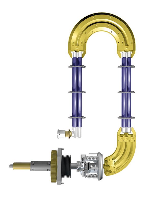
Dosing pumps
Dosing pumps
Dosing pumps are used in many applications, in laboratories and within industry. Often we see the needs, when we require dose liquids under specific conditions:
- High pressure dosing (reaction chambers, aparatures)
- High temperatures dosing
- Injection of reactive substances
- Dosing of viscous media
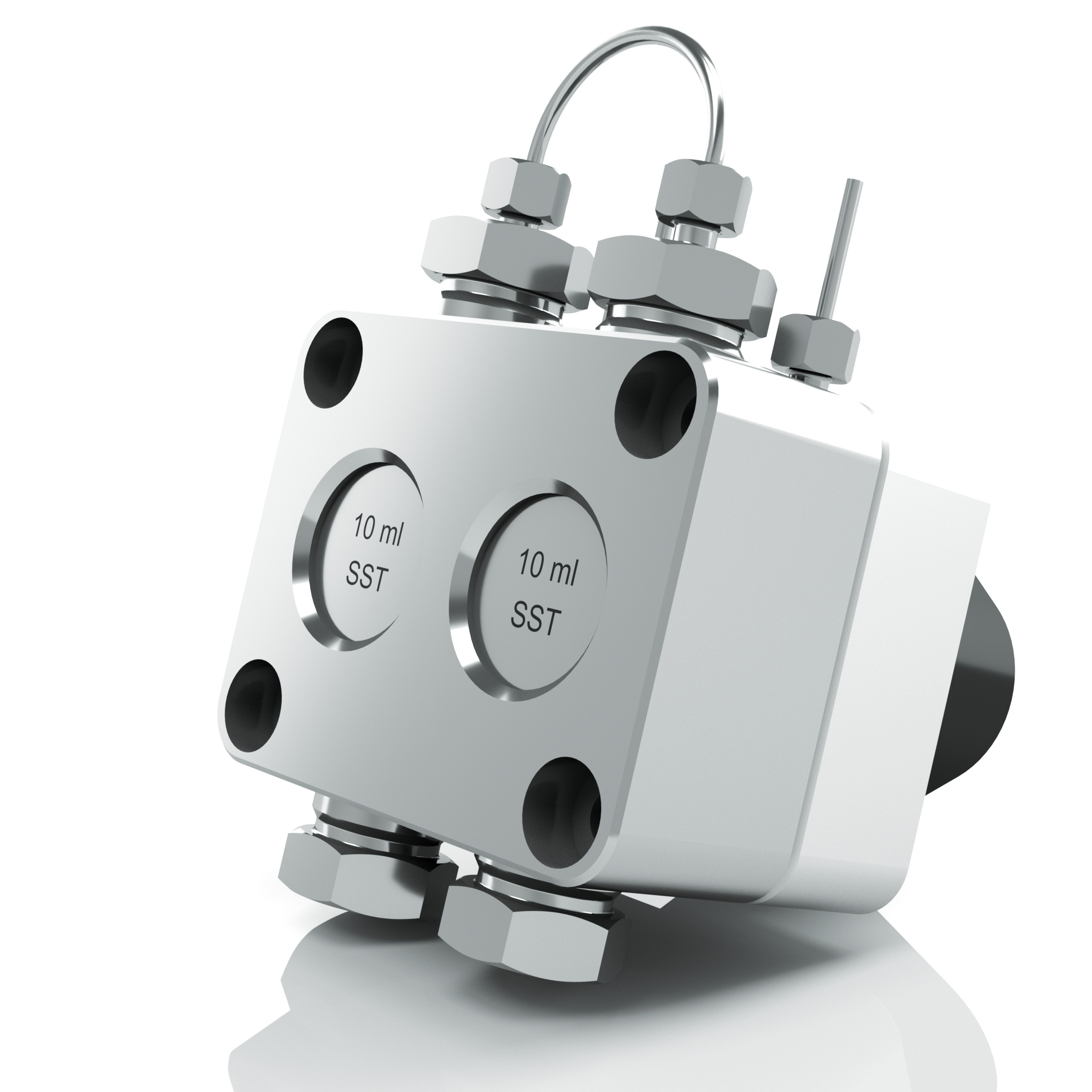 For all above mentioned applications it is possible to use technology that has been proven in the area of high performance liquid chromatography (HPLC). These are double-piston pumps AZURA (Knauer), which use sphire pistons enabling precise continuous dosing under high pressure. These pumps can work with flow of 0,01 to 1000 ml/min, under temperatures of -10°C to +120°C and with viscous media up to 1000 mPa.s.
The pumps can be especially equipped so they can be used in specific application like hazardous areas.
Nice example of use of AZURA pumps is dosing of sulphur trioxide in production of methanesulfonic acid (MSA).
Materials
Pump head are available in following materials:
- Ceramic
- Hastelloy C-276
- Stainless steel
- Titanum
- Stainless steel/Titanum
Further information about models are available here.
TOPAZ Liners
 True Blue Performance
Exceptionally inert, Topaz™ inlet liners, with a new state-of-the-art deactivation,improve trace level analysis.
- Increase accuracy and precision.
- Lower detection limits.
- Use wool with confidence.
When faced with complex choices, simple solutions stand out. TOPAZ™ inlet liners from Restek use a comprehensive, state-of-the-art deactivation and are the only blue liners on the market-making them an easy-to-recognize solution to common inlet problems.
The innovative deactivation used for TOPAZ™ liners results in exceptional inertness for a wide range of analyte chemistries. By reducing active sites and enhancing analyte transfer to the column, these liners increase accuracy and precision, allowing lower detection limits for many active compounds. In addition to improved data quality, you’ll benefit from fewer liner changes and less downtime for maintenance.
Selecting the right liner for your application can be a challenging task. TOPAZ™ inlet liners make the choice simple; the comprehensive deactivation, distinctive colour, and availability in popular configurations mean TOPAZ™ liners are the best choice for optimizing chromatographic performance. Regardless of your application, TOPAZ™ liners provide reliable inertness and assured performance, dayafter-day and analysis-after-analysis.
puriFlash RP
About Flash column stationary phases
Here you will find more information about stationary phases used in reversed phase Flash chromatography.
Reversed phases
puriFl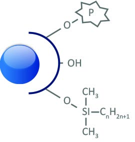 ash® RP-AQ
60Å - 500 m2/g
15 & 30 μm
RP-alkyl, 6% Carbon
End-capping: mixed
pH stability: 2.0 to 7.5
Separation/purification of strongly and moderately polar molecules.
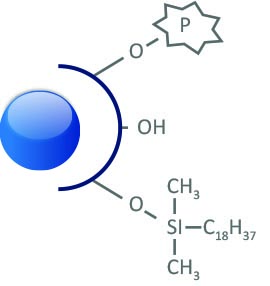
puriFlash® C18-AQ
100Å - 300 m2/g
5, 10, 15 & 30 μm
C18 mono-functional, 14% Carbon
End-capping: mixed
pH stability: 2.0 to 7.5
Separation/purification of moderately polar and non-polar molecules.
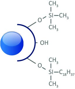
puriFlash® C18-HP
100Å - 300 m2/g
5, 10, 15, 30 & 50 μm
C18 mono-functional, 16,5% Carbon
End-capping: one-step
pH stability: 1.5 to 7.5
This is an excellent choice for routine reverse phase purifications.
Uptisphere® Strategy™ C18-HQ
100Å - 425 m2/g
1.7, 2.2, 3, 5, 10, 15 μm
C18 mono-functional, 19% Carbon
End-capping: multi-step
pH stability: 1.0 to 10.0
Suitable for many pharmaceutical applications and routine methods.

puriFlash® C18-XS
100Å - 300 m2/g
5, 10, 3, 15 & 30 μm
C18 mono-functional, 17% Carbon
End-capping: multi-step
pH stability: 1.0 to 10.0
It is an excellent phase for the complete separation of basic molecules.
There are mor phases available. Contact us for more information for suitable stationary phase for Flahs/Purification chromatography.
Preparative LC
 Task for preparative HPLC systems differs to analytical one. While analytical HPLC task is qualitative and quantitative determination of defined compounds in samples, preparative HPLC task is separation, purification and isolation of value products from mixtures.
Preparative chromatography can be devidet into three main areas:
- Semi-preparative separations
- Batch preparative chromatography (pilot or industrial scale)
- True Counter-current chromatography
- Simulated moving bed (SMB)
- Continuous chromatography
Scale definition
| Parameter | Analytical | Semi-preparative | Preparative |
|---|---|---|---|
| Column sizes (mm) | 120 - 250 x 2 - 4.6 | 120 - 250 x 8 - 16 | 120 - 250 x 20 - 62 |
| Particle size (µm) | up to 5 | 5 - 10 | higher than 10 |
| Stationary phase (g) | up to 5 | 5 - 30 | 50 - 450 |
| Tubings | 1/16" | 1/16" | 1/8" |
| Flow rates (ml/min) | 0.1 - 2 | 5 - 50 | 100 - 1000 |
| Sample size (mg) | 0.01 - 2 | 0.1 - 50 | 1 - 700 |
| Flow cell (mm) | 10 | 3 | 0.5 - 2 |
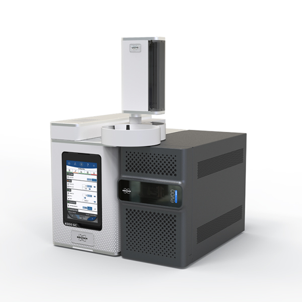
How the Triple Quadrupole works?
 The principle of Triple Quadrupole (TQ) is explained on EVOQ™ system by Bruker. The key points of the system are:
- Axial Ion Source
- Active Focusing Q1
- Lens-Free Ion Path
- 180° Collision Cell
- Elliptical Design
- Off Axis Detector

UHPLC Reagents
 The UHPLC technology requires far better quality solvents than what is currently available on the market. Biosolve ULC/MS solvents, buffers and acids line combine the highest demands for:
- UV low gradient drift
- Minimal peak impurities
- Lowest ionic background in MS detection
- Less than 100 ppb of Alkali metal
ULC/MS solvents, are micro filtered at 0,1 µm, have a residue after evaporation of max. 1 ppm and are packed under inert gas for better shelf-life. Besides the standard 2,5 l packaging, Biosolve is now offering for nano LC/MS:
- 500 ml bottles of acetonitrile, methanol, and isopropanol
- 1 l bottle of water
- 100 ml TFA
Information about the reagencies are available. Just ask for it.
Čištění injektoru
INJEKTOR
- Udává se, že příčinu 85-90% problémů při analýze lze najít v inletu. Proto nezapomínejte pravidelně vyměňovat všechen spotřební materiál. Liner, septum i veškerá těsnění mají omezenou životnost!
- Někdy však výměna spotřebního materiálu ani zaříznutí kolony nestačí. Pak je nutno vyčistit inlet. Obecné pokyny naleznete níže, ale vždy se řiďte především pokyny svého výrobce!
Čištění
- Inlet zchlaďte. Teplota by neměla přesahovat 40°C.
- Vypněte průtok nosného plynu.
- Deinstalujte případný autosampler.
- Deinstalujte kolonu.
- Otevřete inlet, vyjměte veškerý spotřební materiál.
- Pokud lze, je vhodnější odpojit splitovou větev pneumatického systému od inletu.
- Inlet nyní sestává pouze z kovové trubky, která může a nemusí být na konci zúžená.
- Existují různé nástroje, které lze použít k čištění (např. Restek). Pomocí takového kartáče a rozpouštědla- methylen chlorid a metanol pohyby dolů a vzhůru vyčistěte inlet.
- Pomocí pipety prostříkněte inlet rozpouštědlem (rozpouštědlo pod inletem zachyťte do kádinky) a ujistěte se, že v inletu nezůstaly žádné částečky nečistot.
- Pro odstranění zbytků rozpouštědla nahřejte inlet na cca 65 °C.
- Reinstalujte splitovou větev pneumatického systému, nainstalujte nový spotřební materiál.
- Zapněte průtok nosného plynu. Zkontrolujte těsnost.
- Před zvýšením teploty nechte inlet alespoň 10minut proplachovat. Odstraníte tak zbytky kyslíku. Předčasným zvýšením teploty může dojít k aktivaci a znehodnocení nového spotřebního materiálu.
Cleaning the detector
FID
Audible noise, random ghost peaks, low sensitivity. These are typical characteristics of dirty FID detector.
The most common cause contamination sulfide is bleeding from the column. Burned stationary phase may be deposited on the nozzle surface of the detector and cause problems. However, the nozzle napalují and other contaminants.
You need to clean your detector?
The above-described problems, however, may not only be caused by contamination of the detector. The steps outlined below will help rule out other potential causes.
The carrier gas and the stationary phase bleeding
Possible source of contamination can be found not only in the detector itself, but also in front of him. Bleeding stationary phase column, septum, inlet contaminated, contaminated carrier gas ... To eliminate this source Blind FIDU corresponding input plug and turn the FID. If the problem ceases, search problem outside detector. No need to replace the liner? Septum? Clean inlet? What is the state column? Do you have a pure carrier gas? You do not have a leak in the system?
Hydrogen and air
Even hydrogen and air used in the sulfide can be a source of contamination. Attention: especially when problems emerged after replacing the cylinder.
Also improper flow / pressure of the two gases can be a source of increased noise and reduced sensitivity to ignition problems sulfide. Make flows through the meter.
Electrical System
I electrical interference may exhibit similar symptoms dirty FID. There may be a defect electrometer, poor contact or interference by other devices in the lab.
Before cleaning
- Make sure to unplug the power cord!
- Remember that the detector may be hot!
- When dismantling FIDU pay attention insulating parts. Use tweezers, whether these parts do not transfer dirt from your hands or gloves. Beware of possible scratches.
- Remember that sometimes it may be easier to change the nozzle before it is cleaned. This is particularly true when the nozzle is heavily contaminated and sharply increases the risk of scratches during nozzle cleaning.
Cleaning
- Remove the nozzle from the sulfide.
- Place it in an ultrasonic bath with water and detergent and ultrazvukujte about 5-10min.
- Use a tool or a suitable thin wire purge nozzle. Be careful. Any scratches may change the shape of the flame, increasing noise or loss of sensitivity.
- Re-insert the nozzle into the ultrasonic bath and ultrazvukujte other 5-10min. From now handling the nozzle use only tweezers.
- Rinse the nozzle with clean water.
- Rinse nozzle small amount of methanol.
- Blow nozzle stream of air or nitrogen.
- Let dry nozzle.
- Seskládejte FID. Pay attention to tightening. When you drag nozzle may cause its deformation!
- After seskládání can connect column. It is appropriate to heat the FID temperature 10 ° C-40 ° C higher than the normal operating temperature of the detector. Note maximum temperature limit FIDU! Note the maximum operating temperature of the column!
How to keep your detector FIT
- A new column is bleeding most. Install the column and into the inlet, as usual, but let the detector end freely in the furnace and condition the column. Then install the column and into the detector.
- Use a good quality, low column bleed.
- Moisture and oxygen in the carrier gas deplete the stationary phase of the column and cause a bleeding. Wear high-purity gases, molecular sieves, traps ... Check the tightness of the gas circuit.
- Use appropriate septa with low bleed and change them often enough.
ECD
ECD is a specific and sensitive detector. Inappropriate behavior, however, can sharply reduce its lifespan. The gradual increase in signal at this detector normal. However, if an increase occurs abruptly or adding more of the symptoms worsening-noise desensitization search problem.
Cleaning
- ECD contains radioactive material, therefore, mandated regular wear tests. It is forbidden to open or to interfere in any way.
- ECD can be cleaned only thermally. Generally, cleaning is performed so that the ECD detector heated to a temperature close to its maximum operating temperature and impurities are burned. Before cleaning, be sure there are no leaks. Raising the temperature takes place gradually. Track signal. Increase the temperature by 10-20 ° C, the signal starts to grow. Wait for the signal to stabilize and begin to decline, then you can again increase the temperature. Upon reaching the desired temperature, wait for the signal to decrease the expected values.
- Follow the instructions of your manufacturer, the procedure may vary.
- If you heat detector installed column exceed the maximum operating temperature of the column or column Deinstall detector and replace the plug.
Do not ruin your detector!
- Use good quality gas intended for ECD.
- Use molecular sieves, traps for purification of gases.
- When potížích- increase in signal noise worse, desensitizing like. Check system for leaks.
- Use quality columns and septa with low bleeding.
Syringe tip selection
The selection of suitable syring tip is mentioned in Hamilton catalogue. Please, ask for this catalogue.
- Pokaż wszystko

Q-sep QuEChERS 2 ml dSPE Tubes 150 mg MgSO4, 50 mg PSA, 50 mg C18, 7.5 mg GCB, 100 pcs
![]() Dostępność: na zapytanie250 €
Dostępność: na zapytanie250 €